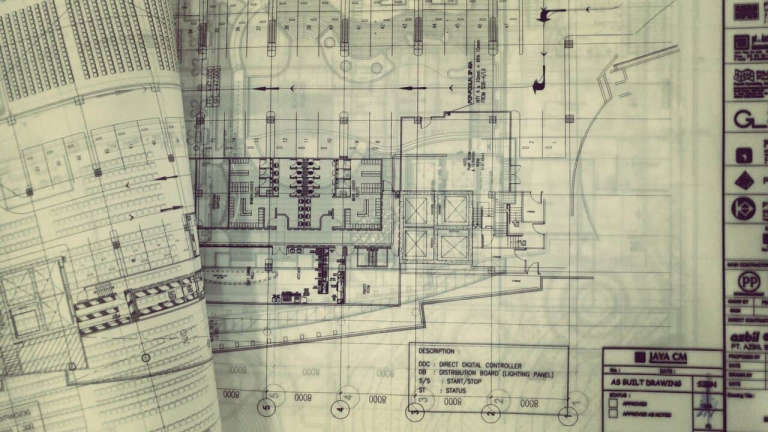
Drawings are a graphical way of representing an idea, a concept, or an entity in a two-dimensional plane. It is one of the oldest forms of communication, dating further back than verbal communication. It communicates all necessary information about an abstract graphic representation relating to a real entity, such as a machine part, building, or tools.
Technical drawings employ the act and discipline of composing drawings that visually communicate how something functions or is constructed. These drawings are essential for sharing ideas in industry and engineering. Technical drawings are utilized for a multitude of purposes. The most common applications of technical drawings are in manufacturing, engineering, and construction.
Who Prepares Drawings?
Both an architect and engineer participate in designing and building a structure. However, the critical difference between an architect and an engineer is that an architect focuses more on the artistry and design of the building, while the engineer focuses more on the technical and structural aspects. Architects design a structure by considering the customer’s needs and requirements. Engineers develop the structure according to the architect’s design, including electrical drawings, structural layout, and plumbing.
Architectural drawings are technical drawings of a building used by architects and others for several purposes. Listed below are some examples of architectural drawings:
- Site plans
- Elevation and building facades
- Cross-section drawings
- Three-dimensional perspective drawings
- Floor plans
- Renderings
Engineering drawings are schematic representations of a building, object, or component made according to precise conventions and intended to aid in the construction or fabrication of the thing depicted. Here are some examples of engineering drawings:
- Structural drawings
- Electrical drawings (i.e., wiring diagrams)
- Mechanical drawings (i.e., plumbing systems, HVAC systems)
- Civil engineering drawings (i.e., site grading, utilities connections, site layout)

A Simple Guide to Engineering Drawings
Technical drawings specify the requirements of components or assembly, which can be complex. Therefore, standardization practices help to provide rules for their specification and interpretation. A single drawing may include many elements with variations to each. Detailed below are the standard foundations present in technical drawings.
Not every line on an engineering drawing is equal. Different types of lines are often used to represent various features, such as hidden edges, centerlines, and border lines.
- “Continuous lines” represent the physical boundaries of an object, or to put simply, are lines for drawing objects.
- “Hidden lines” can show something that would not otherwise be visible on the drawings are represented by dashes.
- “Centre lines” are used to show holes and the symmetric properties of parts. Its long-short-long alternating line patterns characterize it.
- “Extension lines” annotate what is being measured. A “dimension line” has two arrowheads between extension lines and the measurement on top.
- “Break lines” indicate that the view has been broken.
Different views are often present in manufacturing drawings, each serving a particular purpose.
- The “isometric view” shows parts as three-dimensional, and the object appears as if it is being viewed from above from one corner. The lines that are vertical and parallel are in their proper length (to scale).
- An “orthographic view” represents a 3-D object using a front, top, and side two-dimensional view to avoid any distortion of lengths.
- “Detailed views” are scaled-up versions of orthographic views.
- An “auxiliary view” is an orthographic view for nonhorizontal or nonvertical planes and helps to present inclined surfaces without distortion.
- A “section view” provides a view of the inside of an object (e.g., to clarify the interior construction of a part that cannot be clearly described with hidden lines in exterior views alone).
- A “cutout view” is like a section view. While a section view shows the cutting of the entire model, the cut-out view is only a tiny portion of the model to help reduce the number of orthographic views in the drawing.
Information blocks are little boxes present at the bottom corner of engineering drawings.
- The “title block” contains basic information about the drawing, such as the title, scale, drawing number, and date.
- The “revision block” is usually at the top right or with the title block and lists all previous revisions of the drawing.
- “Bill of Materials (BOM) block” is an extensive list of raw materials, components, and instructions required to construct, manufacture, or repair a product or service.
In Summary
Most engineering projects start as drawings that convey details about a project by building. It enables engineers to visualize and communicate complex ideas accurately, eliminating errors and misunderstandings. By providing a clear and detailed representation of the final product, technical drawings help to ensure that everyone working on the project understands the design intent. Additionally, these technical drawings help provide clear guidance throughout the lifecycle of any project by visually communicating how something is constructed and/or functions.
At PSC Biotech, we understand the importance of accurate and detailed technical drawings in engineering projects. That’s why we use the latest technology and software to create high-quality technical drawings that communicate complex ideas clearly and effectively.
Contact us today to learn more about how our technical drawing services can help ensure the success of your project.
Let PSC Biotech experts help you in your projects.


